Synchronous Generator
An alternating current machine in which the frequency of the generated voltages and the speed of the machine are in a constant ratio. IEC 60050.
Synchronous Generator in PSP-UFU
Synchronous generators are the power source for load flow and stability calculations, and they are also one of the main contributors to fault currents.
Only buses that have this element connected can be considered reference buses. PV buses must contain either a synchronous generator or a synchronous motor (synchronous condenser).
The data form is divided into two sections: the first for general, load flow, and fault data, and the second for stability data. The latter also allows access to synchronous machine controls handled by the control editor.
The data regarding the positive sequence impedances of the synchronous generator entered in the “Fault” tab are used both for short-circuit studies and for harmonic studies.
These data are ignored in load flow studies (not used in this study) and in stability studies (data entered in a specific stability form are used).
Synchronous Generator in load flow
The synchronous generator is the power source in PSP-UFU’s load flow study. Its behavior differs depending on the type of bus connected:
- Reference bus: The entered active and reactive power data are ignored, as this element will be used to complete the power balance in the load flow study;
- PV bus: The active power data is considered, but the reactive power data is ignored. The reactive power value is used to keep the voltage magnitude constant at the connected bus;
- PQ bus: For generators connected to this bus, both the entered active and reactive power values are considered.
Synchronous Generator in short-circuit study
While generators in the load flow study are modeled only by currents injected into the buses, for short-circuit analysis a voltage behind an impedance is used. The figure below shows the current path and equivalent circuit of each sequence in the generators.

The generated voltages are only positive sequence, since the generator always supplies balanced three-phase voltages. Therefore, the positive sequence network consists of a pre-fault voltage behind a positive sequence impedance. The negative and zero sequence networks contain no electromotive forces but include the generator’s negative and zero sequence impedances.
The current flowing through the impedance between neutral and ground is . From figure (c) above, it can be seen that the zero sequence voltage drop from point a to ground () is:
The zero sequence network, which is a single-phase circuit assumed to carry only zero sequence current, must therefore have an impedance defined by the following equation:
If the generator is not grounded, no zero sequence current will flow through it. In this case, depending on the transformer connection near the ungrounded generator, the following error message may be displayed:
This happens because the zero sequence admittance matrix is singular. To work around this issue, choose one of the two solutions below:
- Check the "Neutral grounded" option and enter a high grounding reactance value (, for example);
- Or, at the generator bus, insert a reactor with a low reactive power value (, for example).
Synchronous Generator in stability study��
The relationship of values observed in proper tests (defined in IEEE Std. 115-2019), called standard parameters, are used to model the synchronous machine in PSP-UFU’s stability study.
Parameters of the synchronous machine that influence quickly the decay of values are called subtransient (denoted by ), those that influence more slowly are called transient (denoted by ), and those that influence continuously are called synchronous parameters (without superscript).
A set of algebraic-differential equations determines the synchronous machine’s behavior in the stability study:
The last two differential equations are the mechanical equations of the machine; the others are electrical equations (see this thesis for more details on these parameters).
Using the transient and subtransient equations, five models of varying complexity can be defined.
The synchronous machine model is automatically selected based on the data provided to the program.
The following models are presented below, including magnetic saturation effects, along with their block diagrams:
- Model 1: Corresponds to a constant voltage behind a direct-axis transient reactance (), requiring no differential equations;
- Model 2: Represents direct-axis transient effects, requiring one differential equation (), block diagram shown below:

- Model 3: Represents direct and quadrature-axis transient effects, requiring two differential equations ( and ), block diagram shown below:

- Model 4: Represents direct and quadrature-axis subtransient effects, requiring three differential equations (, , and ), block diagram shown below:

- Model 5: Represents direct and quadrature-axis subtransient effects, requiring four differential equations (, , , and ), block diagram shown below:

In all models, the mechanical differential equations are solved.
Saturation
To mathematically represent the effect of saturation in synchronous machine equations, “saturation factors” are introduced that modify the impedances of the equivalent circuit, depending on an effective leakage reactance called Potier reactance ().
This reactance can be obtained through tests (using open-circuit and zero power factor load saturation curves) or approximately estimated from other machine parameters. The leakage reactance (), here approximated by , represents the portion of the machine reactance originating from magnetic flux traveling mostly through air, and therefore independent of saturation.
The implemented method reproduces saturation in both axes (direct and quadrature), which differ due to air gap size differences. It is assumed that the vector sum of the two saturated flux components is in phase with the m.m.f. and proportional to the Potier Voltage (, i.e., voltage behind Potier reactance).
Thus, two saturation factors are used internally: one in the direct axis () and another in the quadrature axis (). These saturation factors are automatically calculated at each integration step and depend on the machine’s saturation curve defined by the saturation factor entered in the data form.
Therefore, the saturated reactances, to be entered into the machine’s algebraic equations, are defined by the following equations:
These equations are also used for transient and subtransient reactances, since the Potier (or leakage) reactance value is not altered.
Infinite bus
Some references include a model without differential equations, where the machine is represented only by a constant voltage behind a direct-axis transient reactance. This is used to represent an infinite bus, which is usually a subsystem much larger than the one being simulated.
In PSP-UFU, an infinite bus can be represented by a machine modeled as Model 1 whose inertia constant (H) is infinite or much larger (, for example) compared to the rest of the system, and the value of is very small (, for example).
Center of inertia
The reference speed is usually taken as synchronous, so in this case This approach, adopted by many stability textbooks, considers as reference a fictitious machine always running at synchronous speed regardless of disturbances applied to the system. In PSP-UFU, the concept of Center of Inertia (COI) is implemented, which is a weighted sum of the speeds of the machines present in the system:
Where: is the number of connected synchronous machines in the system.
Applying the COI results in output data, such as rotor angle, that are easier to analyze. In the program’s implementation, the use of this feature is optional and can be set by the user.
Synchronous generator data form
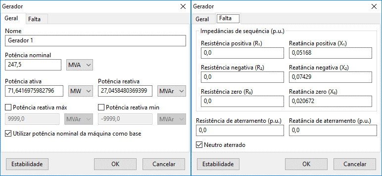
The image below shows the insertion/editing form for synchronous generator data:

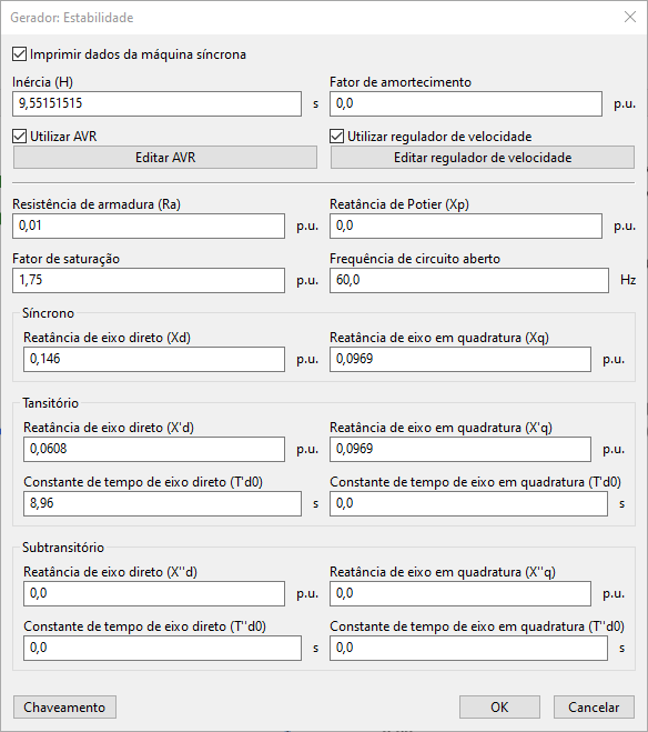
The second section contains stability data, as shown below, accessed by clicking the "Stability" button in the main form. Here you can also access synchronous machine controls managed by the control editor.

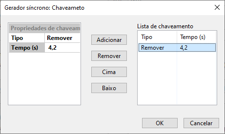
In the stability form, the "Switching" button can be seen in the lower left corner. This form, common to several other elements, allows inserting and/or removing the generator during the stability study.

- General
- Fault
- Stability Button
- Switching Button
Name
Identification of the electrical element. Any number of characters can be entered in the Unicode standard.
All PSP-UFU power components have this field.
Rated power
Rated power of the generator, entered in MVA, kVA, or VA.
This field is especially important if the "Use nominal power as base" option is checked.
Active and reactive power
Active (entered in W, kW, MW, or p.u.) and reactive (entered in var, kvar, Mvar, or p.u.) power of the generator.
If the connected bus is PV, the reactive power value is ignored; if it is a reference bus, both values are ignored.
If more than one generator is connected to the same bus, the reactive power (in reference and PV buses) and active power (in reference buses) values are equally distributed, respecting the individual reactive power limits.
Maximum and minimum reactive power
Maximum and minimum reactive power limits of the generator for voltage control on PV buses. If these values are exceeded, the unit’s reactive power will be limited to the entered value and the connected bus will be converted to PQ, no longer controlling the set voltage.
Use nominal power as base
If this option is checked, the program will use the generator’s nominal power as the base for unit conversion, including those in the stability form; otherwise, the system base power is used.
Sequence impedances
Resistance and reactance values for fault current calculations. Positive, negative, and zero sequence data are entered.
Grounding impedance
Values used for phase-to-ground and double-phase-to-ground fault calculations. If the generator neutral is not grounded, the value entered in this field is ignored.
Neutral grounded
Indicates whether the generator neutral is grounded.
Print synchronous machine data
Displays synchronous generator data in time-domain plots. The following data are displayed:
- terminal voltage
- active and reactive powers
- mechanical power
- frequency
- field voltage
- angle .
Use AVR and speed governor
These fields enable or disable the synchronous machine controls, such as turbine and exciter models.
If selected, the controls can be inserted and modified via the “Edit AVR” and “Edit speed governor” buttons, which access the PSP-UFU control editor.
Armature resistance
Synchronous machine armature resistance, in
Potier reactance
Potier reactance for saturation calculation, in
Saturation factor
Value used in the calculation of the saturation curve.
Represents the field current value (in ) required to reach 1.2 p.u. terminal voltage.
This value must be greater than 1.2, or it will cause simulation errors. If not specified, the machine saturation is not considered in calculations.
Open-circuit frequency
Indicates the machine speed when starting the simulation disconnected from the grid.
This information is particularly useful for analyzing the connection of out-of-step generators to the grid.
Synchronous reactances
Steady-state synchronous reactance values of the machine. Direct and quadrature-axis values should be equal or very close for cylindrical-rotor machines, while salient-pole machines have distinct values.
Transient reactances and time constants
Transient parameters of the synchronous machine in or seconds.
The direct-axis transient reactance value must be nonzero, or the program will produce an error.
The number of entered parameters determines the model used internally by the program.
Subtransient reactances and time constants
Subtransient parameters of the synchronous machine in or seconds, detailing the presence of damper windings. Like transient data, these parameters define the machine model.
The "Switching" button opens a form, common to several other elements, that allows inserting and/or removing the generator during the stability study.
In this form, a generic list of line insertions and removals over time can be created, customized by switching property contexts where the switching type (insertion or removal) and the event time (in seconds) are edited. These properties are added and removed from the generic list via the "Add" and "Remove" buttons, respectively.
Access to synchronous machine controls
As mentioned earlier, the synchronous machine’s voltage and speed regulators can be enabled or disabled via the "Use AVR and speed governor" checkboxes. Both options will access the control editor.
Access to AVR controls can then be created and manipulated by clicking the "Edit AVR" button, and the Speed Governor is accessed via the "Edit speed governor" button.
In PSP-UFU, the option to edit the AVR covers more than just the machine’s voltage control. It must include the synchronous machine’s control loop as well as the synchronous machine exciter. Optional control strategies, such as PSS (Power System Stabilizer) and/or over- and under-excitation controls, are also implemented together.
As with the AVR, the Speed Governor covers more than just primary speed regulation. This option must include at least the primary speed control loop as well as the turbine model. Optional speed control strategies are also inserted here.
References
- MILANO, F. Power System Modelling and Scripting. London: Springer, 2010. doi: https://doi.org/10.1007/978-3-642-13669-6
- ARRILLAGA, J.; WATSON, N. R. Computer Modelling of Electrical Power Systems. Wiley & Sons, New York, 2001. doi: https://doi.org/10.1002/9781118878286
- KUNDUR, P. Power System Stability and Control. McGraw-Hill, New York, 1994.
- DOMMEL, H. W.; SATO, N. Fast Transient Stability Solutions. IEEE Transactions on Power Apparatus and Systems, v. PAS-91, n. 4, Jul 1972, p. 1643-1650. doi: https://doi.org/10.1109/TPAS.1972.293341
- IEEE Std 1110-2002 IEEE Guide for Synchronous Generator Modeling Practices and Applications in Power System Stability Analyses. IEEE, New York, Nov. 2003. doi: https://doi.org/10.1109/IEEESTD.2003.94408
- KIMBARK, E. W. Power System Stability: Volume III – Synchronous Machine. New York: Wiley-IEEE Press, 1995.