Bus
Low-impedance conductor to which several electric circuits can be connected at separate points.
Note – In many cases, the bus consists of a bar. IEC 60050.
Bus in PSP-UFU
The bus element, or simply busbar, is a connector or node in the PSP-UFU single-line diagram.
This bus can represent a PCC (Point of Common Coupling), a distribution pole, a substation, a substation bus, among many other types of analysis and connection points between elements.
Bus editing form
The bus must be the first electrical element inserted in the power diagram, since all other power components are connected to it.
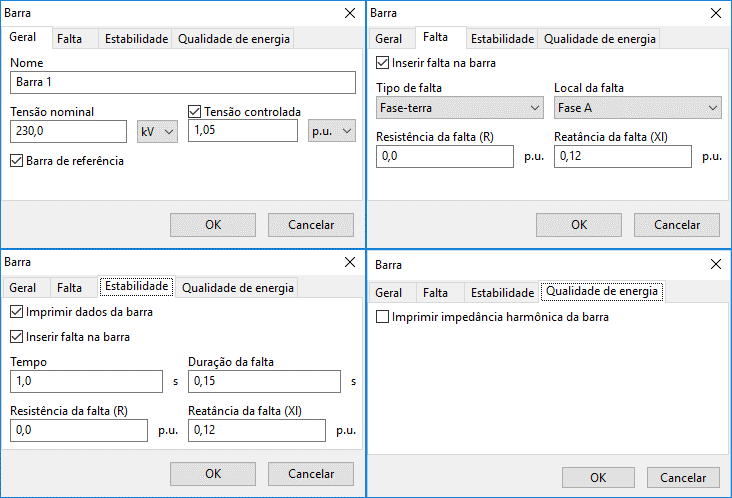
The figure below shows the bus data insertion/editing form:

This form is subdivided into four different contexts:
- General: where general bus information and load flow data are entered;
- Fault: where the shunt short-circuit must be inserted;
- Stability: containing options for displaying bus data in time-domain plots and inserting three-phase faults in transient stability calculations;
- Power Quality: contains the option to display the harmonic impedance seen by the bus.
- General
- Fault
- Stability
- Power Quality
Name
Electrical element identification. Any number of characters can be entered using the Unicode standard.
All PSP-UFU power components have this field.
Nominal voltage
Used to calculate the base impedance of some connected elements, as well as the transformer turns ratio between buses.
Its unit can be selected, expressed in V or kV.
Changing this parameter will modify the entire voltage of the segment connected by electrical lines, and a warning is issued to the user.
Controlled voltage
Characterizes the bus as a voltage-controlled bus (PV Bus).
This option is only valid if a synchronous machine is connected; otherwise, the value is ignored.
If the reactive power limit of the connected synchronous machine is exceeded, this value is also ignored.
The value can be entered in p.u. or in volts (or kV if the nominal voltage is in this unit).
Slack bus
Characterizes the bus as a slack bus (Swing Bus).
This option is only valid if a synchronous generator is connected; otherwise, an error message will appear during program calculations.
Insert fault
Indicates whether there is a short-circuit at the bus in short-circuit studies.
Note that this option will insert a fault for the short-circuit calculation and will not be considered in the stability study.
Fault type
Selects the type of bus shunt fault:
- three-phase to ground
- phase-to-phase
- phase-to-phase-to-ground
- single-phase-to-ground
Fault location
Selects the phase(s) where the fault occurs (or their combination in two-phase faults); this option is disabled for three-phase faults.
Fault resistance and reactance
Represents the fault impedance.
Solid short-circuits (zero-impedance faults) are represented by entering zero in both fields.
Print data
Displays the edited bus data in the transient stability study plot.
The following data are shown:
- bus voltage magnitude
- bus voltage angle
Insert fault
Inserts a three-phase fault at the bus in the stability calculation.
This option will insert a fault for the stability calculation and will not be considered in the short-circuit study.
Time
Time instant () when the fault occurs during stability studies.
This and the following fields are only accessible if a fault is inserted in the stability study.
Fault duration
Duration of the inserted fault () in the stability study.
The fault starts at and is cleared at .
Fault resistance and reactance
Fault impedance in stability studies.
A solid fault is represented by inserting a very low shunt impedance ().
Print bus harmonic impedance
Prints the harmonic impedance seen by this bus in the Frequency Response study.
Summary of how to define bus type:
- To define the bus as a PQ Bus, the options "Slack bus" and "Controlled voltage" must be unchecked;
- To define the bus as a PV Bus, check only the "Controlled voltage" option, leaving "Slack bus" unchecked;
- To define the bus as a Slack Bus, check the "Slack bus" option.
If "Controlled voltage" is unchecked, a controlled voltage of is assumed.
The system must have only one slack bus.