Simulation Settings
Simulation parameterizations and settings are accessed in the Simulation menu by clicking the Simulation Settings button icon.

Simulation Settings Edit Form
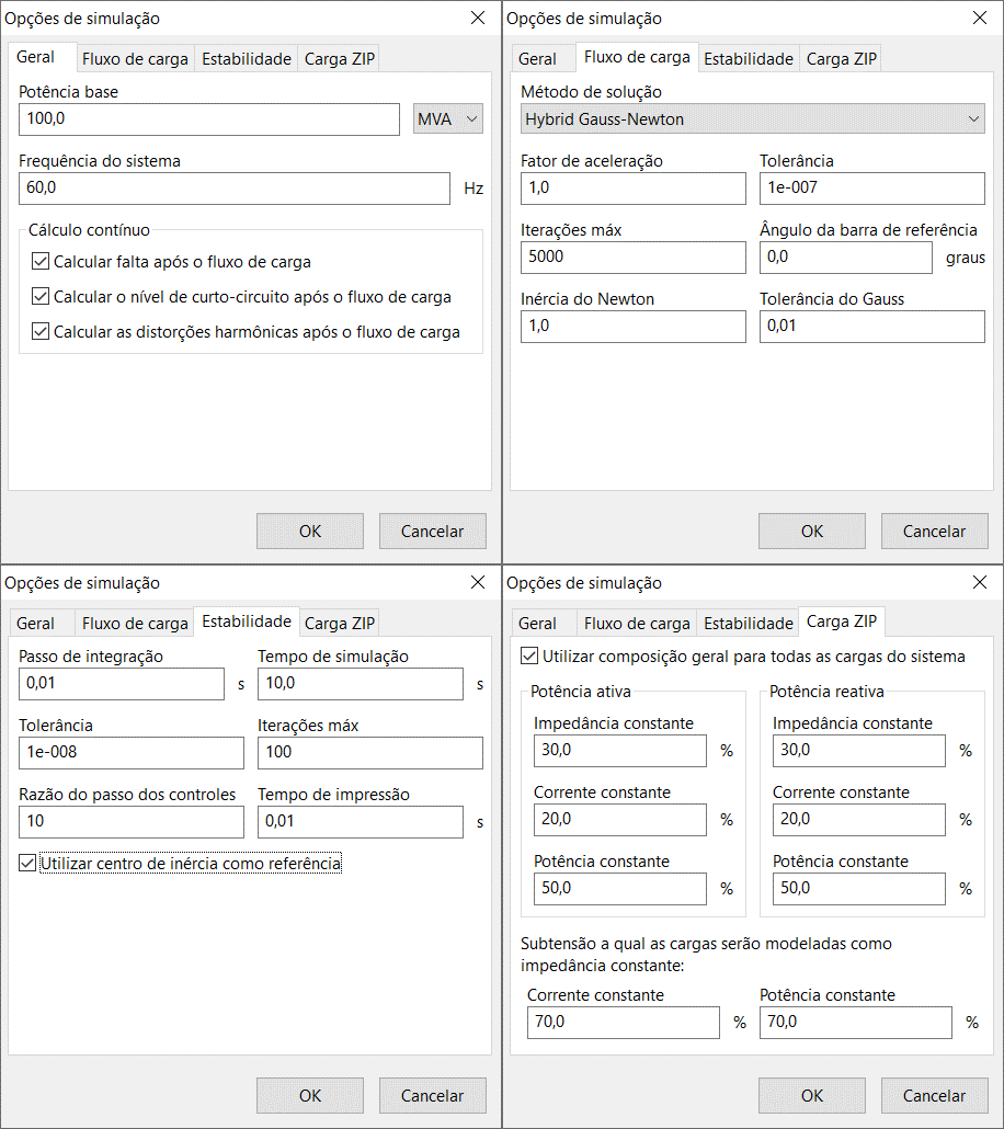
The image below shows the simulation settings edit form:

This form is subdivided into four distinct contexts:
- General: where general and common information to various simulations is entered;
- Power Flow: where the numerical solution method is selected, as well as its parameters;
- Stability: containing time simulation options and parameters of the integration method;
- ZIP Load: contains general options of ZIP loads in the stability study.
- General
- Power Flow
- Stability
- ZIP Load
Base Power
Base power of the system used for conversion of real data into and vice versa. Can be entered in VA, kVA, or MVA.
The base power of each element can be different from the system base power. To do this, just check the option "Use nominal power [of the element] as base," present in their respective data edit forms.
System Frequency
Defines the nominal frequency of the system.
When changing the nominal frequency, pay attention to the "Open Circuit Frequency" field of synchronous machines.
Continuous Calculation
Enables or disables continuous calculation for short circuit, short circuit level, and harmonic distortions calculations. Continuous calculation for power flow is always enabled.
To enable continuous calculation, press the Enable Solution button present in the Simulation menu.
With this option, the selected static calculations are automatically performed when modifying any network parameters, such as electrical data and breaker operation (removal or insertion).
Solution Method
Defines the numerical solution method for the power flow study. Currently, the PSP-UFU includes the following methods:
Acceleration Factor
Factor used to speed up convergence in Gauss methods. The use of the acceleration factor is done through the equation:
Where:
- is the complex voltage of the current iteration with acceleration factor applied
- is the complex voltage of the current iteration
- is the complex voltage of the previous iteration with acceleration factor applied
- is the acceleration factor
This option is enabled only for the Gauss-Seidel and Hybrid Gauss-Newton methods.
Tolerance
It is the error value between iterations (in ) at which the numerical method convergence is reached.
For the Gauss-Seidel method, the error is calculated by the largest magnitude of the difference between voltages in the previous and current iteration (); while for the Newton-Raphson method, this error is the magnitude of the largest power adjustment ( or ).
Max Iterations
Maximum number of iterations a method can reach. If this value is reached, the power flow calculation is stopped with an error.
Reference Bus Angle
The value of the angle of the reference bus, in degrees.
Newton Inertia
Value that multiplies the power corrections. Values greater than increase the correction, and values less than decrease the correction.
Values less than may help convergence, but increase the number of iterations and consequently the processing time of the method.
This option is enabled only for the Newton-Raphson method.
Gauss Tolerance
Defines the tolerance of the Gauss-Seidel for the hybrid method. This option is enabled only for the Hybrid Gauss-Newton method.
Since Newton-Raphson is considerably sensitive to initial conditions, the first iterations are calculated using Gauss-Seidel until the error is less than the tolerance specified in the “Gauss Tolerance” field. From that point, the calculation is done using the Newton-Raphson method until convergence is achieved with an error smaller than the tolerance stipulated in the “Tolerance” field.
This option helps convergence of systems that cannot be solved using conventional Newton-Raphson.
Integration Step
Defines the integration step for the Implicit Trapezoidal integration method.
Very high values may generate simulation errors, while very small values will significantly increase the processing time of the stability calculation.
Simulation Time
Defines the total simulation time, in seconds.
Tolerance
Tolerance of the iterative process (in ) of the Implicit Trapezoidal integration method.
Max Iterations
Maximum number of iterations of the iterative process of the Implicit Trapezoidal integration method. If the number of iterations exceeds this value, the stability calculation will be stopped with an error.
Control Step Ratio
Defines the number of integration steps the control system will undergo for each integration step of the power system.
For example, if the integration step is set to and the step ratio is , the effective integration step for the control systems will be (10 times smaller).
The use of this field is justified in situations of large differences in the time constants of synchronous machines (usually larger) and control systems (usually smaller).
A control step ratio value of will not alter the control system's integration step.
Printing Time
Interval at which the program will store data for printing in time graphs.
Very small values (less than ) may significantly increase the processing time of the stability calculation.
The printing time must be greater than or equal to the integration step.
Use general composition for all system loads
Enables the composition of the ZIP load for all loads that do not have individual parameterization.
Load Composition (active and reactive powers)
Defines the composition, in percentage, of the Impedance, Current, and Constant Power components of the load. This composition can be implemented individually for active and reactive power.
The sum of the ZIP load components for a power must be 100%, otherwise an error message will be displayed.
Undervoltage at which loads are modeled as constant impedance
Defines the percentage voltage value () below which the load is considered as pure constant impedance.
Constant current and power loads have problems at very low voltages. As the voltage decreases, the currents of these loads do not decrease, resulting in loss of precision and problems in convergence of iterative processes. To circumvent this problem, a predefined voltage () is used, at which constant current and power loads (or components) are modeled as constant impedance.