Synchronous Condenser
A synchronous machine operating without mechanical load and supplying or absorbing reactive power. free translation - IEC 60050.
Synchronous Condenser in PSP-UFU
The synchronous condenser is simply a synchronous motor operating without load on its shaft with the purpose of supplying or absorbing reactive power in the network. Regarding load flow, in PSP-UFU this element behaves identically to the synchronous generator, but its active power is entered into the solution algorithms with a negative sign.
Its parameterization for load flow, fault, and harmonics studies is identical to that of the synchronous generator.
It is possible to use a synchronous generator with zero or negative active power to represent the synchronous condenser in stability studies.
Synchronous Condenser Data Form
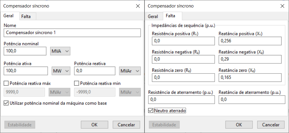
The image below shows the insertion/editing form for synchronous condenser data:

- General
- Fault
Name
Identification of the electrical element. Any number of characters can be entered in the Unicode standard.
All PSP-UFU power components have this field.
Rated power
Rated power of the condenser, entered in MVA, kVA, or VA.
This field is especially important if the "Use nominal power as base" option is checked.
Active and reactive power
Active power (entered in W, kW, MW, or p.u.) and reactive power (entered in var, kvar, Mvar, or p.u.) of the condenser.
If the connected bus is PV, the reactive power value is ignored; if it is a reference bus, both entered values are ignored.
If more than one condenser is connected to the same bus, the reactive power values (in reference and PV buses) and active power values (in reference buses) are equally distributed, respecting the individual reactive power limits.
Maximum and minimum reactive power
Maximum and minimum reactive power limits of the condenser for voltage control on PV buses. If these values are exceeded, the reactive power generated by the unit will be limited to the entered value, and the connected bus will be converted to PQ, no longer controlling the set voltage.
Use nominal power as base
If this option is checked, the program will use the condenser's nominal power as the base for unit conversion, including those in the stability form; otherwise, the system base power is used.
Sequence impedances
Resistance and reactance values for fault current calculations. Positive, negative, and zero sequence data are entered.
Grounding impedance
Values used for phase-to-ground and double-phase-to-ground fault calculations. If the generator neutral is not grounded, the value entered in this field is ignored.
Neutral grounded
Indicates whether the generator neutral is grounded.