Induction Motor
An asynchronous machine of which only one winding is energized. IEC 60050.
Three-phase induction motor in PSP-UFU
In PSP-UFU, induction motors are included in load flow and stability studies.
The stability data of the induction machine are used together with the load flow, correctly calculating the reactive power of the machines and consequently the voltage at the connected bus.
When selecting the option "Calculate reactive power in load flow", the correct data must be entered in the "Stability" tab, otherwise an incorrect reactive power will be assigned to the motor.
Three-phase induction motor in load flow calculation
The figure below shows the model of a simple cage three-phase induction motor (IM).

The active and reactive powers can be calculated in relation to the motor variables and parameters in as:
As seen in the above equations, there are four variables and only two equations. In practice, the variables can be reduced to three since the voltage magnitude (V) is obtained from the power flow results.
To solve the equations, one more variable must be defined. In PSP-UFU, the chosen fixed variable is active power (P), as it provides numerically correct and suitable results for motors under stability conditions.
Thus, in this static model, active power is kept constant during load flow calculation, and slip (s) is updated at each iteration. The active power equation can be rewritten in terms of slip:
Where:
This model can be inserted into the load flow solution by following these steps:
- Calculate constants to . These values remain constant throughout the solution;
- In each iteration, calculate coefficients , , and using the updated value of ;
- Solve the quadratic equation to obtain two values of ; choose the larger one as it is in the stable region of the torque-slip characteristic;
- Using the new value, obtain the reactive power (). The power vector is updated and conventional load flow solution steps are executed.
Steps 2 to 4 are repeated until convergence is achieved.
In PSP-UFU, induction motors are not considered in short-circuit calculations.
Three-phase induction motor in stability study
An important dynamic load is the induction motor since it accounts for a significant share of system loads.
The induction machine model presented earlier, which can operate as both motor and generator, is well established in the literature.
As described in the previous section, initialization of this machine is done together with the power flow since the reactive power required by the induction machine depends on motor parameters as well as bus voltage. This approach is necessary because conventional methods lead to incorrect results in heavily loaded systems.
The induction machine motion equation must be expressed in terms of torque, not power, as done with synchronous machines. Rotor symmetry means angular position is not important, and slip () is used instead of speed (), where:
Neglecting friction and windage losses and shaft power, the mechanical equations of the motor are expressed as:
Where:
- = mechanical torque
- = electrical torque
- = inertia of the motor–mechanical load set
The terms , , and define the load mechanical torque behavior according to slip. Mechanical torque normally varies with speed, which can be expressed proportionally by the quadratic equation:
Where:
The electrical equations of the simple cage induction motor are based on the equivalent circuit from the previous figure.
Similarly to the synchronous machine transient model, the induction motor can be represented by the Thevenin equivalent circuit of transient voltage behind a stator resistance and transient reactance . The blocked-rotor apparent transient reactance is:
The rotor open-circuit time constant () is:
And the open-circuit reactance is:
Since the reactances are unaffected by rotor position, the DAEs of the induction motor can be expressed directly in real () and imaginary () components. The complete model is thus represented by the following system of differential-algebraic equations:
Induction motor data editing form
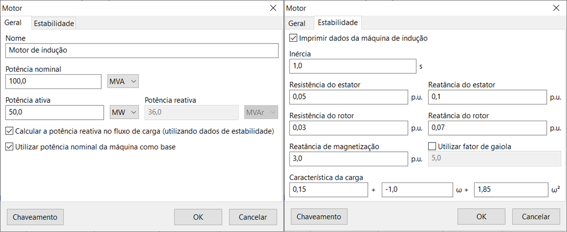
The figure below shows the data insertion/editing form for induction motors:

The form includes the "Switching" button in the lower-left corner.
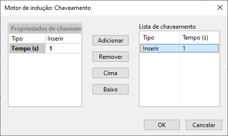
This form, common to several other elements, allows the insertion and/or removal of the motor during the stability study.

- General
- Stability
- Switching Button
Name
Electrical element identification. Any number of characters can be entered using the Unicode standard.
All PSP-UFU power components have this field.
Rated power
Motor rated power, entered in MVA, kVA, or VA.
This field is especially important if the "Use rated power as base" option is checked.
Active and reactive powers
Motor active power (entered in W, kW, MW, or ) and reactive power (entered in var, kvar, Mvar, or ).
If the “Calculate reactive power in load flow” option is enabled, the reactive power field is disabled for editing.
Calculate reactive power in load flow
If selected, the program uses the stability form data to calculate the motor’s reactive power during the iterative load flow process.
If this option is not used, the motor will be considered a constant power load in the load flow study.
Not using this option may cause steady-state errors in the stability study.
Use rated power as base
If selected, the program uses the motor’s rated power as the base for unit conversion, including those in the stability form; otherwise, the system base power is used.
Print induction machine data
Displays induction motor data in time-domain plots. The following data are shown:
- terminal voltage
- active and reactive powers
- current, electrical torque
- mechanical torque
- speed
- slip
Inertia
Inertia of the motor-load set, in seconds.
Stator resistance and reactance
Stator resistance and reactance of the induction motor, in
Rotor resistance and reactance
Rotor resistance and reactance of the induction motor, in
Magnetizing reactance
Magnetizing branch reactance of the induction motor, in
Use cage factor
Allows inserting a cage factor () in the induction motor.
This factor increases rotor resistance under high slip conditions, as in double-cage or deep-bar motors. Rotor resistance follows:
Where:
- = rotor resistance entered in the form.
Load characteristic
Describes the mechanical load torque characteristic on the motor shaft according to the mechanical torque equation:
The sum of the coefficients () must be equal to one.
The "Switching" button opens a form, common to several other elements, allowing insertion and/or removal of the motor during the stability study.
In this form, a generic list of insertions and removals over time can be created, customized by a switching properties context where the switching type (insertion or removal) and event time (in seconds) are edited. These properties are added or removed from the list using the "Add" and "Remove" buttons, respectively.
References
- SÁNCHEZ, J. C.; OLIVARES, T. I. A.; ORTIZ, G. R.; VEGA, D. R. Induction Motor Static Models for Power Flow and Voltage Stability Studies. In: IEEE Power and Energy Society General Meeting, 2012, San Diego. doi: https://doi.org/10.1109/PESGM.2012.6345618
- IEEE Std 399-1997. IEEE Recommended Practice for Industrial and Commercial Power Systems Analysis (Brown Book). IEEE, New York, Aug. 1998. doi: https://doi.org/10.1109/IEEESTD.1998.88568
- MILANO, F. Power System Modelling and Scripting. London: Springer, 2010. doi: https://doi.org/10.1007/978-3-642-13669-6
- ARRILLAGA, J.; WATSON, N. R. Computer Modelling of Electrical Power Systems. Wiley & Sons, New York, 2001. doi: https://doi.org/10.1002/9781118878286