Harmonics
Two harmonic-related tools were developed in PSP-UFU:
- Total Harmonic Distortion of Voltage (THD);
- Frequency Response.
The Total Harmonic Distortion tool calculates the harmonic voltages caused by harmonic current sources, as well as the THD of all buses in the system.
The Frequency Response tool (or frequency sweep analysis) involves varying the network impedance over a frequency spectrum observed from a certain bus.
Frequency sweep analysis is widely used in harmonic filter design.
A series arrangement of a line without shunt susceptances, a bus, and a capacitor can be used to create a passive filter in harmonic studies. In future versions, a passive filter element will be implemented in PSP-UFU.
In the current version, changes in system resistance caused by skin effect are not considered. Future versions will include this feature.
Running the harmonic calculation in PSP-UFU
After building the single-line diagram in the power editor, the harmonic distortion calculation is executed in the Simulation menu by clicking the Harmonic Distortions button.
To access the frequency sweep tool, click the Frequency Response button.

Harmonic Distortions
Clicking the "Harmonic Distortions" button calculates the distortions caused by harmonic current sources in all system buses.
If no harmonic current sources are inserted into the power system, the voltage distortion of all buses will be .
Another possibility is execution via continuous calculation, also available in the Simulation menu by clicking Enable solution.
With this option, the selected static calculations in simulation settings are automatically executed when any network parameter is modified, such as electrical data or breaker operations (insertion/removal of elements).
THD level calculations are not enabled by default in continuous calculation and must be selected in the simulation settings.
The harmonic distortion results are displayed in linked text elements and when hovering the mouse over a bus.
Frequency Response
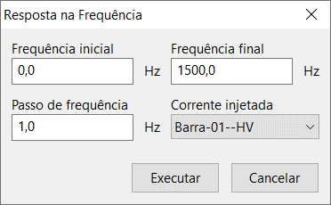
Clicking the "Frequency Response" button opens a form to enter tool parameters:

Initial frequency
Defines the initial sweep frequency.
Final frequency
Defines the final sweep frequency.
Frequency step
Defines the step increment of the frequency.
Smaller steps generate more precise plots but may increase execution time.
Injected current
Defines the bus where the harmonic current will be injected for analysis.
This field can be interpreted as:
"The response of the harmonic impedances seen by the system buses if a harmonic current source exists at the selected bus".
Execute button
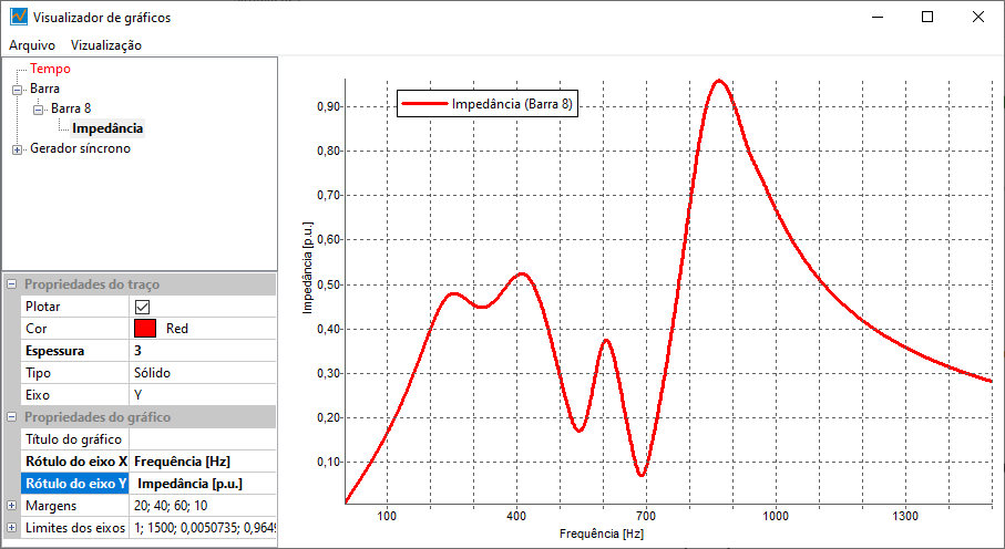
Clicking the execute button performs the sweep and displays results in the graph viewer, as shown below:

To view the harmonic impedance sweep of a bus, this option must be enabled in its data edit form.
Harmonic tool calculations
Both calculations are based on the following matrix equation:
Where:
- = Vector of harmonic currents injected into buses
- = Harmonic bus admittance matrix
- = Vector of harmonic voltages at buses
- = Harmonic order
The harmonic current vector is defined in the program using the “harmonic current source” element, where the user can create a list of currents (in A and/or ) injected into a bus.
The program automatically defines harmonic orders in the simulation by analyzing all harmonic current source lists before calculations.
Harmonic admittances are calculated by multiplying the fundamental inductive reactances () and capacitive susceptances () of each element by the harmonic orders:
Once harmonic admittances are calculated, the same conventional models and algorithms are used to construct .
The matrix equation is solved using Gaussian elimination to avoid inverting each harmonic admittance matrix, making the calculation computationally efficient.
Once harmonic voltages are calculated, the THD at a generic bus can be defined as:
In the Frequency Response tool, a sinusoidal current is injected into the bus across a frequency range, and the matrix equations are used to calculate the voltage response. This is repeated at discrete steps over the specified spectrum.
The program uses the positive-sequence admittance matrix and a positive-sequence injected current to calculate impedances directly in p.u.
References
- ARRILLAGA, J.; WATSON, N. R. Power System Harmonics. John Wiley & Sons; Chichester, 2003. doi: https://doi.org/10.1002/0470871229