Line
A manufactured transmission medium used to transmit electromagnetic energy between two points with minimal radiation. free translation - IEC 60050.
Line in PSP-UFU
Lines in PSP-UFU are balanced models. They can be used as transmission and distribution lines in power systems.
The figure below shows the model implemented in PSP-UFU:

Where:
- is the line resistance;
- is the line inductive reactance;
- is the line shunt capacitive susceptance.
The model used in PSP-UFU is balanced and does not have mutual impedances between phases.
The line can be inserted with anchoring points, or "nodes," for greater graphical customization of the element, as shown in the CAD Tools.
The line must be inserted between two buses of the same nominal voltage. If you try to insert it between buses of different voltages, an error message will be displayed.
A series arrangement of a line without the shunt susceptances, a bus, and a capacitor can be used to build a passive filter in harmonic studies. In future versions, a passive filter element will be implemented in PSP-UFU.
Line editing form
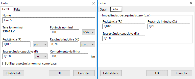
The image below shows the insertion/modification form for transmission line data:

This form is subdivided into two distinct contexts:
- General: where general line information and load flow data are entered;
- Fault: where zero sequence impedances are entered.
The parameters needed to build the line according to its model are entered in the General tab, used to build the positive and negative sequence admittance matrix.
Additional zero sequence impedance data necessary for unbalanced short-circuit calculations are edited in the Fault tab, used in the construction of the zero sequence admittance matrix.
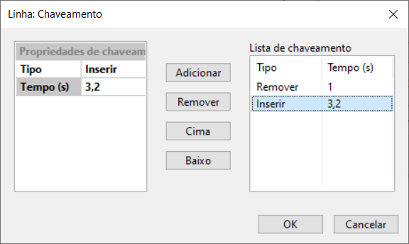
Besides these two contexts, there is a "Stability" button at the bottom left of the form. This form, common to several other elements, allows insertion and/or removal of the line during stability studies.

- General
- Fault
- Stability Button
Name
Identification of the electrical element. Any number of characters can be entered using the Unicode standard.
All power components in PSP-UFU have this field.
Nominal voltage
Non-editable field showing the nominal voltage of the line. To change this field, it is necessary to edit the corresponding field of the connected bus.
Nominal power
Nominal power of the line, entered in MVA, kVA, or VA.
This field is especially important if the option "Use nominal power as base" is checked.
Parameters of the model
Resistance (), series inductive reactance (), and total shunt capacitive susceptance () present in the line's model.
These parameters are entered in , or ( or for ).
Line length
Used to calculate the value of line parameters entered in (or ).
The line length is ignored if units per kilometer are not used.
Use nominal power as base
If this option is checked, the program will use the nominal power of the line as the base for unit conversion; otherwise, the system base power will be used.
Zero sequence model parameters
These parameters are necessary for the correct calculation of unbalanced faults (phase-phase, phase-phase-ground, and phase-ground) currents and must be entered in
Failure to enter these data will result in incorrect results for unbalanced faults.
The "Stability" button will open a form, common to several other elements, that allows insertion and/or removal of the line during stability studies.
In this form, a generic list of line insertions and removals over time can be created, customized by a switching property context where the switching type (insertion or removal) and the event instant (in seconds) are edited. These properties are added to and removed from the generic list via the "Add" and "Remove" buttons, respectively.