Transformer
A static device with two or more windings that, by electromagnetic induction, transforms a system of alternating voltage and current into another system of voltage and current generally of different values and at the same frequency, with the purpose of transmitting electrical energy. free translation - IEC 60050.
Transformer in PSP-UFU
Transformers with any connections and phase shifts between primary and secondary voltages can be inserted in PSP-UFU. For this, transformers must be modeled representing their tap () and phase shift (), using an ideal transformer with transformation ratio in series with its impedance (), where is a complex number ().
The model used in PSP-UFU does not consider the magnetizing branch or mutual impedances between phases.
The figure below shows the transformer model implemented in PSP-UFU:

Where:
- is the total transformer resistance;
- is the total inductive reactance of the transformer;
- is the complex tap of the transformer.
The relationship between the voltages and currents of generic buses and is given by the matrix equation:
As in lines, the two-winding transformer must be inserted between buses, but the nominal voltages of these buses do not need to be identical.
The first selected bus will be the primary side, which is indicated by a circle. To change the primary side after insertion, simply disconnect the transformer nodes and reconnect them switching the buses, using the CAD tools.
Transformers in short-circuit studies
Just as in load flow studies, the representation of system elements for short-circuit studies is done through equivalent circuits inserted into the bus admittance matrix. In unbalanced faults it is necessary to form three sequence admittance matrices: positive, negative, and zero.
The positive sequence admittance matrix is built the same way as in load flow studies. In the negative sequence, the phase shift angle between primary and secondary voltages () must be inverted, since negative sequence phasors are displaced in the opposite direction. Thus, the matrix representing the admittances in the previous equation must be replaced by the following expression:
The negative sequence impedance in transformers must be treated specifically due to different types of connections. The figure below shows the equivalent circuits for each type of two-winding transformer connection. The arrows indicate possible paths for zero-sequence current flow.

For transformers with grounded wye connection, if the neutral-to-ground connection has an impedance , the zero sequence equivalent circuit must have an impedance of in series with the equivalent resistance and reactance of the transformer.
Transformer Data Editing Form
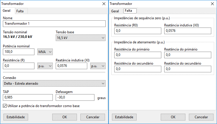
The image below shows the data insertion/modification form for transformers:

This form is subdivided into two distinct contexts:
- General: where general transformer information, load flow data, its connection, and phase shift are entered;
- Fault: where zero sequence impedances and grounding impedances are entered.
Besides these two contexts, the "Stability" button can be seen in the lower left of the form. This form, common to several other elements, allows insertion and/or removal of the transformer during the stability study.

- General
- Fault
- Stability Button
Name
Identification of the electrical element. Any number of characters can be entered in Unicode standard.
All power components in PSP-UFU have this field.
Nominal voltage
Non-editable field showing the primary and secondary voltage of the transformer. To change this field, the corresponding field in the connected bus must be edited.
Base voltage
Voltage used to convert the entered impedance parameters from to The voltages selected by a dropdown box are edited in the connected bus forms.
Base voltage is ignored if the data entered is already in
Rated power
Transformer rated power, entered in MVA, kVA, or VA.
This field is especially important if the option "Use rated power as base" is selected.
Transformer impedance
Transformer series impedance (resistance and inductive reactance), entered in or . If impedances are entered in , the selected base voltage will be used for conversion to
Connection
Transformer connection used for zero sequence current calculation in unbalanced faults involving ground (phase-ground and phase-phase-ground).
The following connections are available:
TAP
Transformer tap relative to the primary.
The tap in PSP-UFU must be entered as the ratio between the nominal primary voltage and the tap voltage .
Phase shift
Transformer phase shift relative to the primary, in degrees. This value is independent of the connection type, so for connections other than (grounded or not) and , the correct phase angle must be entered.
Use rated power as base
If this option is selected, the program will use the transformer's rated power as the base for unit conversion; otherwise, the system base power will be used.
Zero sequence impedance of transformer
These parameters are necessary for the correct calculation of currents in unbalanced faults (phase-phase, phase-phase-ground, and phase-ground) and must be entered in
Failure to enter these data will result in incorrect results for unbalanced faults.
Grounding impedances
Grounding impedances are only used for connection and must be entered in
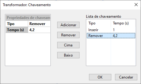
The "Stability" button will open a form, common to several other elements, which allows insertion and/or removal of the transformer during the stability study.
In this form, a generic list of insertions and removals of the line over time can be created, customized by a switching property context where the switching type (insertion or removal) and the instant (in seconds) of the event are edited. These properties are added and removed from the generic list using the "Add" and "Remove" buttons, respectively.