Load
- the active, reactive or apparent power generated, transmitted or distributed within a system;
- the power demanded by a group of consumers classified according to their particularities and characteristics, for example, heating load, daytime reactive load, etc. free translation - IEC 60050.
Load in PSP-UFU
Loads are generic power-consuming elements. In load flow studies, it is possible to model the load as constant power or constant impedance, and in stability studies, the load can be composed in the desired proportion of three types (ZIP load): constant power, constant impedance, and constant current.
Constant power loads in load flow studies are inserted into the power vector and remain fixed throughout the simulation.
Shunt elements, such as reactors, capacitor banks, and constant impedance loads, are represented simply by their shunt admittances. Since input parameters generally consist of their nominal active (P) and reactive (Q) powers (in the case of reactors and capacitors, P=0), their admittance must be found with the equation below to be inserted into the admittance matrix:
For short-circuit and harmonic studies, loads are modeled as constant impedance, regardless of the setting indicated in their data editing form.
Load in stability study
Exact modeling of system loads becomes impractical in stability problems, given the large number and variety of components involved, as well as changes in their compositions caused by various factors such as time, weather conditions, and economy. Therefore, several approximations must be used when formulating a load model in these studies.
An interesting way to represent voltage-dependent loads are ZIP loads, which are quadratic functions, having three components: constant impedance (Z), constant current (I), and constant power (P). Active and reactive powers are obtained by the following equations:
Where:
and are the active and reactive powers of the ZIP load, respectively, connected to a generic bus i;
is the current voltage at a generic bus i;
is the initial voltage at a generic bus i, obtained from the load flow study;
and are the constant impedance components for active and reactive powers, respectively;
and are the constant current components for active and reactive powers, respectively;
and are the constant power components for active and reactive powers, respectively.
The values of the ZIP load power components are obtained using the load powers after load flow convergence ( for active power and for reactive power), using the following expressions:
The values of , and represent the composition in constant impedance, constant current, and constant power, respectively, of the active power component of the load, which are entered by the user as percentages, with the sum of these three values necessarily equal to 100%. The parameters , and can be interpreted analogously but compose the reactive power component of the load.
The behavior of the powers, obtained from PSP-UFU simulations, of each component that makes up the ZIP load is shown in the figure below.

Constant current and power loads have problems at very low voltages. As voltage decreases, the currents of these loads do not decrease, as shown in the figure above, resulting in loss of accuracy and convergence problems in iterative processes. To overcome this problem, a user-defined voltage () is used, below which the constant current and power loads (or components) are modeled as constant impedance, resulting in the power and current behavior shown in the figure above.
Load editing form
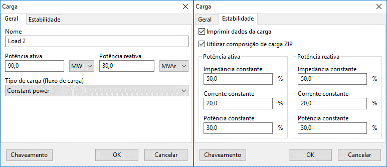
The image below shows the data insertion/modification form for loads:

This form is subdivided into two distinct contexts:
- General: where general load information, type of load and load flow data are entered;
- Stability: containing options to display load data in time plots and options for ZIP load parameterization.
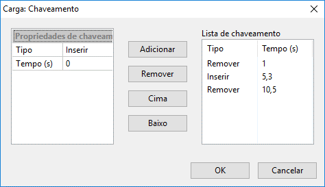
Besides these two contexts, there is a "Switching" button at the bottom left of the form. This form, common to several other elements, allows insertion and/or removal of the load during stability studies.

- General
- Stability
- Switching Button
Name
Identification of the electrical element. Any number of characters can be entered using the Unicode standard.
All power components in PSP-UFU have this field.
Active power
Active power component of the load. Can be entered in MW, kW, W, or (system base).
Reactive power
Reactive power component of the load. Can be entered in Mvar, kvar, var, or (system base).
Load type (load flow)
Type of load for load flow study, two types can be selected: Constant power and Constant impedance. Constant power loads are inserted into the power vectors and remain invariant in the calculation, while constant impedance loads have their impedance value determined using the power and nominal voltage, which is inserted into the admittance matrix.
Print data
Displays load data on time plots. The following data are displayed:
- voltage magnitude
- current
- active and reactive powers.
Use ZIP load composition
Allows composing the ZIP load for stability studies. If this option is not selected, the global composition defined in the simulation settings is used.
By default, all loads in PSP-UFU are defined as constant impedance in the stability study.
If all buses have the same ZIP load behavior, the parameterization can be done in the simulation settings for all loads, without individual parameterization.
Active and reactive power composition
Values of the ZIP load composition, entered separately for active and reactive power, in percentage. The composition sum must be equal to 100%, otherwise an error message will be displayed to the user.
The "Switching" button opens a form, common to several other elements, that allows insertion and/or removal of the transformer during stability studies.
In this form, a generic list of insertions and removals of the line over time can be created, customized by a switching properties context where the switching type (insertion or removal) and the event instant (in seconds) are edited. These properties are added and removed from the generic list via the "Add" and "Remove" buttons, respectively.