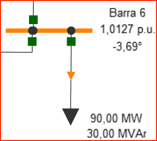
Linked Text
The linked text element (to the power element) can be inserted in the power elements editor. This text element can be linked to numerous results and parameters of the power system.
This element is useful for identifying and analyzing the results of power elements.
Another important application is updating its value when applying “continuous solution” in the project, helping visualize changes in the power grid’s state.
The results presented by these elements can also be used together with the single-line diagram when creating project reports.

Inserting text elements in PSP-UFU
Through the Tools submenu, you can insert text elements, as shown in the image below.

By selecting the "Text" button or using the "A" shortcut key, the user must click the desired position in the workspace. This will add a temporary element with the value "Text". To configure this element, double-click on it.
The text element, like control elements, does not automatically display the data editing form when inserted for the first time.
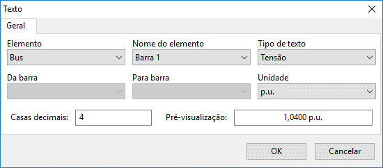
Text element data editing form
The figure below shows the data editing form for this graphic component.

Its configuration is carried out through fields that associate the component with the electrical power elements, in addition to the numeric result format. The fields are enabled as previous data is entered, and an error message is displayed if any required parameter is not filled in.
The association process begins by choosing the type of power element that will be linked to the text. Next, a list is displayed with the name of all components previously inserted in the power elements editor of the type defined in the previous field, thus associating the text with the element.
In “Text type” you define what output will be displayed. This field depends on the type of element selected, as shown in the table below. Some other data are required for branch elements, such as source and destination buses, to represent the correct power and current flow. Finally, the user must enter the number of decimal places for numeric data. A preview can be seen in the form.
| Power Element | Text Type | Available Units |
|---|---|---|
| Bus | Name Voltage Angle Fault current Fault voltage Short-circuit level Voltage THD | - , V, kV Degrees, Radians , A, kA , V, kV , VA, kVA, MVA % |
| Generator | Name Active power Reactive power Fault current | - , W, kW, MW , var, kvar, Mvar , A, kA |
| Line and transformer | Name Active power flow Reactive power flow Losses Current Fault current | - , W, kW, MW , var, kvar, Mvar , W, kW, MW , A, kA , A, kA |
| Load, Induction Motor and Synchronous Condenser | Name Active power Reactive power | - , W, kW, MW , var, kvar, Mvar |
| Capacitor and Inductor | Name Reactive power | - , var, kvar, Mvar |
Once inserted, these text elements can be manipulated in the same way as power elements.