Control Editor
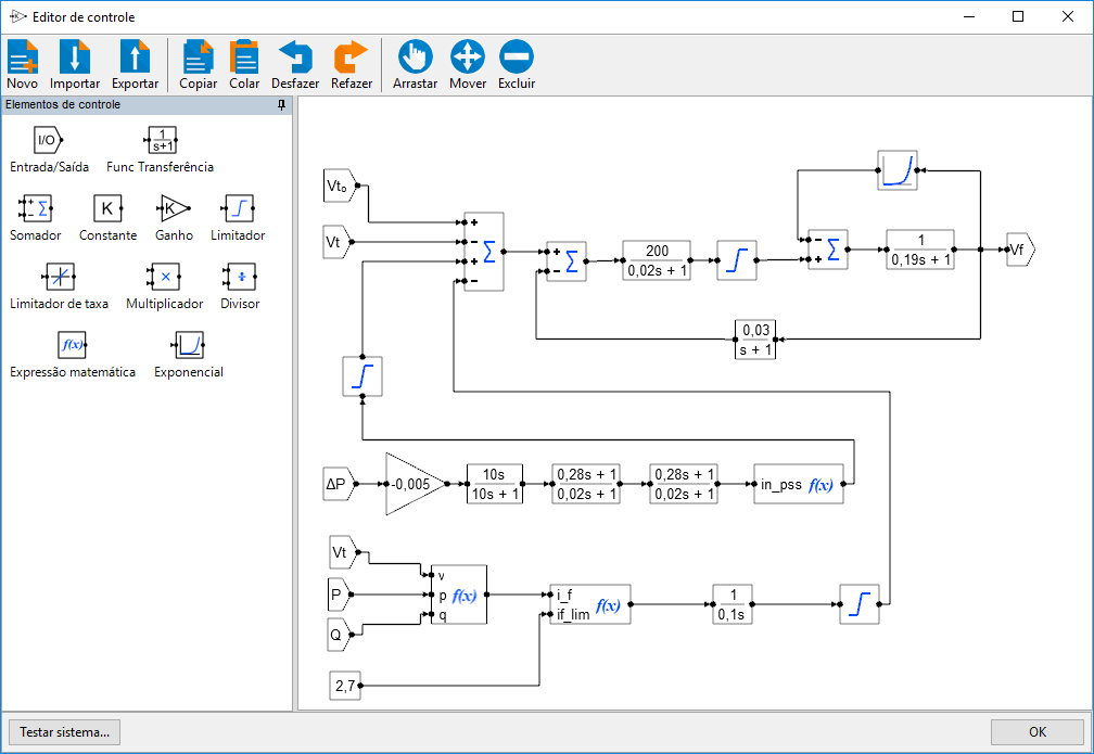
The controls of synchronous machines are created, modified, imported, and exported in a separate editor from the power elements, shown in the figure below.

Access to the editor is done through two buttons present in the synchronous generator stability data editing form:
In PSP-UFU, the AVR editing option involves more than just the machine voltage control. It must include the machine control loop as well as the synchronous machine exciter. Other (optional) control strategies, such as PSS (Power System Stabilizer) and/or over- and under-excitation controls, are also implemented together (as shown in the previous figure).
As with the AVR, the Speed Governor involves more than just the primary regulation of the machine. In this option, you must include at least the primary speed regulation control loop as well as the turbine model. Optional speed control strategies are also added in this option.
Control Elements
Access to control elements is done in a (detachable and dockable) window via related icons.
Once the user clicks the desired icon, the control element follows the mouse pointer until it is placed in the desired position by clicking again in the workspace. The elements are then connected by “connection lines” inserted by clicking on the nodes of previously added components, allowing the construction of a generic control network.
The manipulation and navigation tools, such as drag, move, and delete, are inherited from the power element editor, with identical behavior. Editing the data of inserted components is also done with a double click on the inserted element, displaying a data editing form.
The following control blocks are present in PSP-UFU:
- Input and Output
- Transfer Function
- Mathematics
- Limiters
- Constants
- Mathematical Expression
Control System Initialization
If the control system inputs have nonzero values or the first operation between them does not result in a zero output, the system needs initialization, so as to adjust the input and output values of elementary blocks and the state vectors of the transfer functions present. This procedure is performed by solving the entire control network until convergence is achieved, i.e., the absolute difference between the same outputs from a previous and a current solution must be zero or very close to zero.
The initialization process is performed automatically by PSP-UFU.
Since initialization is imposed by the control inputs, convergence errors may occur due to poor parameterization of the power and control system elements.
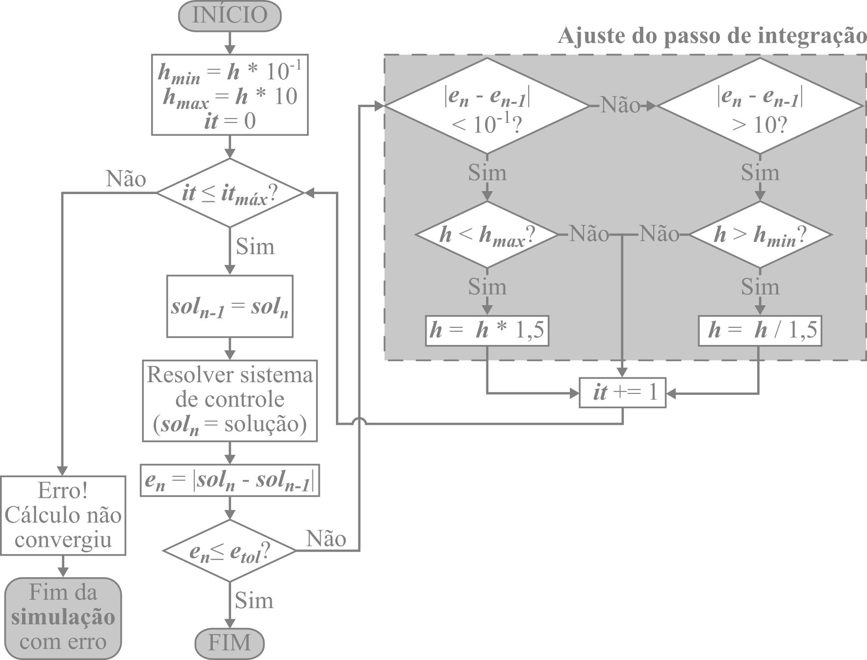
To optimize and improve the stability of the initialization process, a variable integration step within limits is used, such that the step increases when the differences between the control system solutions are smaller, and decreases when this difference becomes large. Implementing this approach significantly reduced process termination with errors caused by numerical instability and sped up initialization.
The flowchart below shows the initialization process implemented in PSP-UFU:

Control Diagram Testing
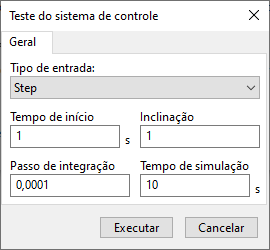
In the lower left corner of the Control Editor is the "Test System..." button. The button opens the control testing form, as shown in the figure below:

In this form, it is possible to define the behavior of all diagram inputs:
-
Input type: Defines one of the possible input types in PSP-UFU: "Step", "Ramp" or "Quadratic";
-
Start time (): Defines the start time in the simulation for the defined input. The initial inputs are always set to zero and take on different values after the start time;
-
Slope (): Value related to the input type:
- For "Step" type input – The slope value defines the final value of the step:
- For "Ramp" type input – defines the slope coefficient of the line:
- For "Quadratic" type input – defines the curve growth coefficient:
-
Integration step (): Step size for the Implicit Trapezoidal integration method;
-
Simulation time (): Total simulation time.
After the simulation, the results are displayed in the graph viewer.
The same input settings are applied to all input blocks in the system.
It is possible to apply multiple different inputs (including with conditionals!) using the mathematical expression block.
Using the mathematical expression block, it is possible to insert complex inputs, such as testing the block diagram (AVR DC1C + PSS1A – IEEE Std. 421.5-2016) shown in the figure below:

