Input / Output
Inputs and outputs are variables related to synchronous machines. Each type of input and output is associated with a machine regulator: Automatic Voltage Regulator (AVR) and Speed Governor (GOV).
Warning!
The control system must have at least one input and one output.
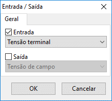
The inputs and outputs of the control system are defined by these blocks, which differ for each type of scope. The figure below shows an example of a form for editing the inputs and outputs of an AVR:

Input and Output Variables
The user must specify the block type as input or output and then select the desired variable from a list. The following control variables are currently available in the program:
- Terminal voltage (input: AVR): Magnitude of the voltage at the synchronous machine bus, in , time-varying. This variable is normally used in calculating the error of the AVR reference voltage;
- Speed (input: AVR and GOV): Speed of the synchronous machine, in rad/s, time-varying. Commonly used in calculating the speed error in speed regulators, as well as input to the PSS in AVRs;
- Active and reactive power (input: AVR): Active power supplied by the synchronous machine, in , time-varying. Usually used as input to the PSS (active power) and for excitation under- and overcurrent control in AVRs;
- Initial terminal voltage (input: AVR): Magnitude of the voltage at the synchronous machine bus prior to the dynamic study, derived from load flow, in , fixed over time. This variable is normally associated with the AVR voltage reference;
- Initial speed (input: AVR and GOV): System speed (), defined in the simulation options, in rad/s, fixed over time. This variable is typically used as the speed reference in SRs and for speed normalization;
- Initial mechanical power (input: GOV): Initial mechanical power, calculated after initialization of synchronous machines using data from the load flow, in , fixed over time. Usually used as the mechanical power reference in speed regulators;
- Variation of speed and active power (input: AVR): Calculation of the variation of these inputs between integration steps normalized by the integration step, according to the equation:
Where:
- is the variation of the input (speed or active power);
- and are the variable at the current and previous step, respectively;
- is the integration step.
InformationNormalization is necessary for the correct use of the control step ratio, defined in the simulation settings.
- Field voltage (output: AVR): Defines the voltage applied to the synchronous machine field, in Used as an output of AVRs, mainly controlling the voltage at the connected bus and/or the machine's power factor;
- Mechanical power (output: SR): Defines the mechanical power applied to the synchronous machine shaft. Used as an output of speed regulators, mainly controlling the active power injected by the machine and its frequency.